
MPR and slab projections
Explore linked axial, coronal and sagittal planes.
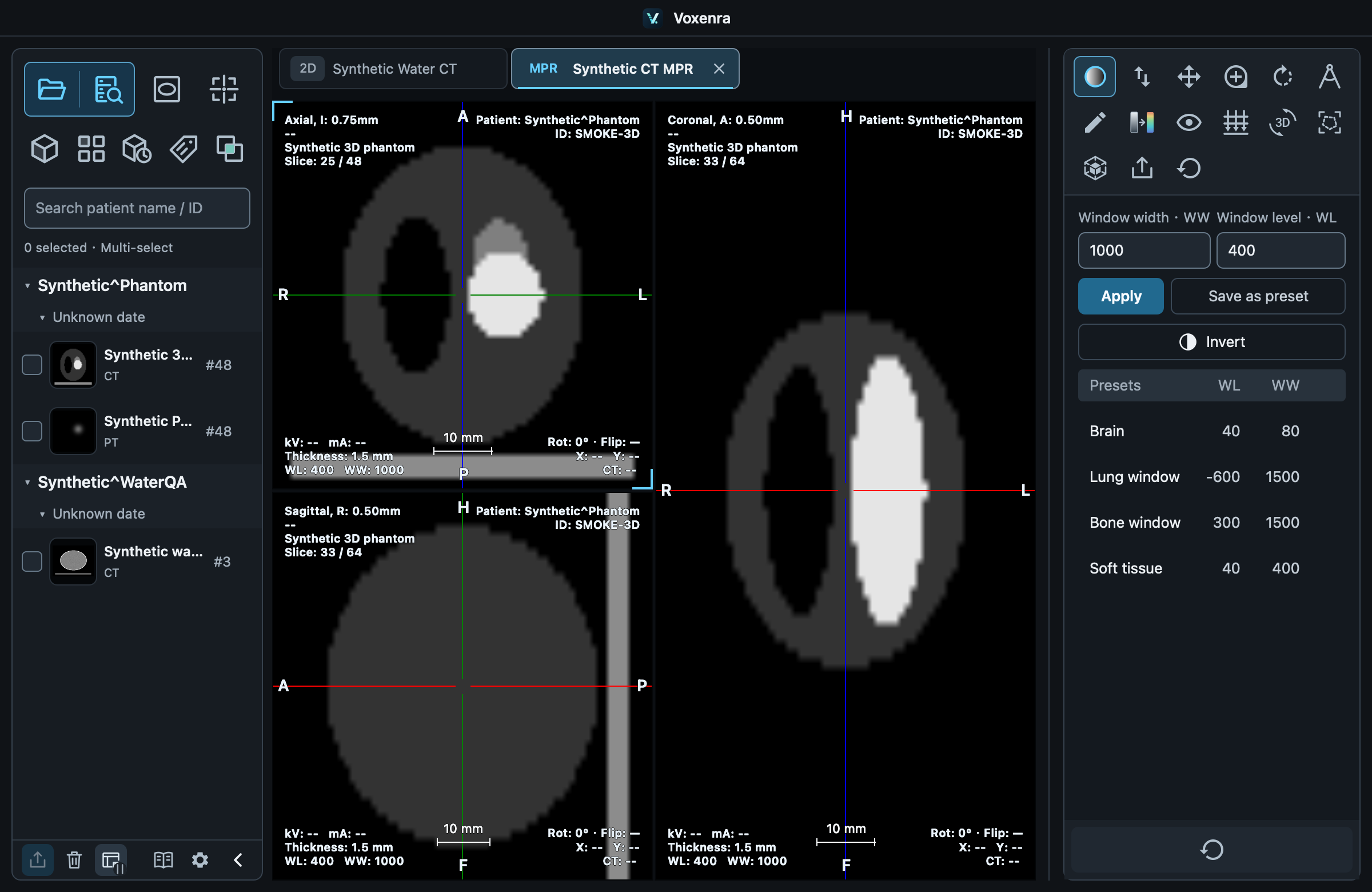
Position and browse
Select a regular volume and open MPR. Click to activate a plane, scroll through it, and drag the crosshair center to reposition in space. Play loops along the active plane’s navigation direction while retaining linked positioning in the other planes. Click again to stop. This is distinct from temporal 4D playback.
Two rotation modes
Drag a crosshair line to rotate the corresponding plane. The 3D rotation tool rotates all three planes around their shared center. The corner position label shows Oblique when a plane departs from the standard patient axial, coronal or sagittal orientation, and restores the corresponding name on return. Independent 3D camera rotation does not rename planes; linked rotation updates names from the actual plane directions.
Slab projection
Choose MIP, MinIP, Mean or Sum and set the slab thickness. Colored boundary lines mark its extent.
During segmentation
Segmentation and VOI tools prioritize drawing and disable slab projection. Switch to a tool such as Windowing before moving or rotating crosshairs.
Choose a layout
Choose horizontal/vertical triplets, a large left/right/top/bottom plane, or four views including 3D in MPR layout. The default is a large right plane. CT, MR, standalone PET MPR and CT 4D support all seven layouts. Switching preserves slices, windows, measurements and annotations; double-click temporarily maximizes a plane. Fusion retains its own layout. Double-click a slice or the 3D cell to maximize it within the viewing area; double-click again to restore the layout without changing the camera or preset.
Four views and 3D positioning
The four-view layout places axial at the top left, coronal at the top right, sagittal at the bottom left and a 3D reference at the bottom right. It reuses the current MPR volume and follows 4D phase changes. Colored outlines mark the intersection of each plane with the volume bounds, using the crosshair colors. A cyan ring marks their common intersection and remains visible inside the volume. Choose intersection only or hide the reference if desired. The outlines mark individual planes, not the full slab thickness. Enable Remember layout to reuse this layout for new views of the same type and remember subsequent changes. MPR and 4D keep separate preferences. Disabling it leaves the current view unchanged and uses the default for new views. Workspace restoration uses each saved tab layout without overwriting the preference.
3D interaction and linked rotation
Click the 3D cell or its title to select it. The right toolbar switches to rotation, pan, zoom, display presets (display settings for PET), six viewing directions, export and reset. Click an MPR plane to return to its tools. Both toolbars provide separate View layout and Viewport settings controls. Drag near the cyan ring to move the MPR intersection in the current camera plane, within the volume bounds. Link 3D and MPR rotation is enabled by default: the reconstructed planes and camera rotate together in either direction. Turn it off in Viewport settings to rotate independently. Pan and zoom remain independent. Layout, active viewport, each tool selection, reference mode, rotation linking and the 3D camera are saved with the workspace. In a 4D tab, the selected 3D view also retains 4D Play. The collapsed toolbar also provides presets, six view directions, layout, and viewport settings controls. Presets open a named list; directions expand into secondary buttons. Reference planes and rotation linking are configured in Viewport settings. The 3D label identifies the target view. Reset 3D view resets its camera and display; enabled rotation linking still propagates camera rotation to MPR. Presets match the modality and are independent of slice windowing. The 3D name appears inside the upper-left corner, follows corner-information visibility, font size and color, and uses no separate header row. CT / MR axial, coronal and sagittal windows are linked; 3D windowing and presets remain independent.